The Internet of Things Using Arduino and the D1 Mini – Course Coming Soon!

A quick announcement of my upcoming tutorial series designed around introducing the Internet of Things (IOT) and creating IOT devices using Arduino and the WeMos D1 Mini.

As well as learning all about both IOT and the D1 Mini (no prior experience necessary), I aim to teach you how to build your very own internet enabled weather station and a WiFi controlled switch that can be controlled via an Amazon Alexa.

Come back soon or subscribe to my YouTube channel to be the first to hear of future announcements…

WeMos D1 Mini

Creepy Halloween Doll

In time for Halloween, an Arduino controlled, WiFi-enabled, creepy animated doll. The doll can be controlled manually using a mobile device or set to 1 of 3 automatic modes in order to surprise your friends! Enjoy the video below for now, more details to follow here shortly…


For now, the 3D printable parts to enable control of the eyes can be found here:

https://www.thingiverse.com/thing:3152317

The micro servos required to control movement of the head and eyes can be purchased here:

https://www.banggood.com/TowerPro-SG90-Mini-Gear-Micro-Servo-9g-For-RC-Airplane-Helicopter-p-1009914.html?p=KF2715792233201409DJ

Blind Controller v2a is here!

AutoBlind_v2a_Final_2018-Sep-20_12-22-33PM-000_CustomizedView2435222859_jpg.jpg

This will be my ‘more than likely’ final update to the blind controller and is available at thingiverse, now with the following features:

  • New improved gear to help prevent chain slips
  • Incorporation of a magnetic sensor in place of the standard cover to enable control of the blinds to be stopped at a precise location
  • Larger gear surround to accommodate magnetic sensor mod
  • Minor tweaks to button surround to facilitate insertion of an m5 nut
  • Left and right hand sided wall mounts
  • New Arduino sketch for use with magnetic sensor

Note: In case you have already printed it, there is no change to the main body and the previous gear cover and button surround should still fit the original design.

New Project – Creepy Halloween Doll

This weekends project, turn a creepy looking doll into an interactive Halloween prop!

DSC00521.JPG

First step, remove the head and attach a motor.

DSC00522.JPG

DSC00523.JPGTwo options were considered, a stepper (above) and a servo. I wanted the head to be able to turn 360 degrees but the stepper motor was too slow. Even though the servo can only rotate 180 degrees, the speed is good and it was also easier to attach so this is what I decided upon.

With the head back in the dolls body (thanks to a lot of hot glue!) it’s time to test, next up will be programming some sort of routine and maybe add some additional theatrics…

Adding a strobe using a transistor and animating specific moves…

Blind Controller Custom PCB Boards – Installation Instructions

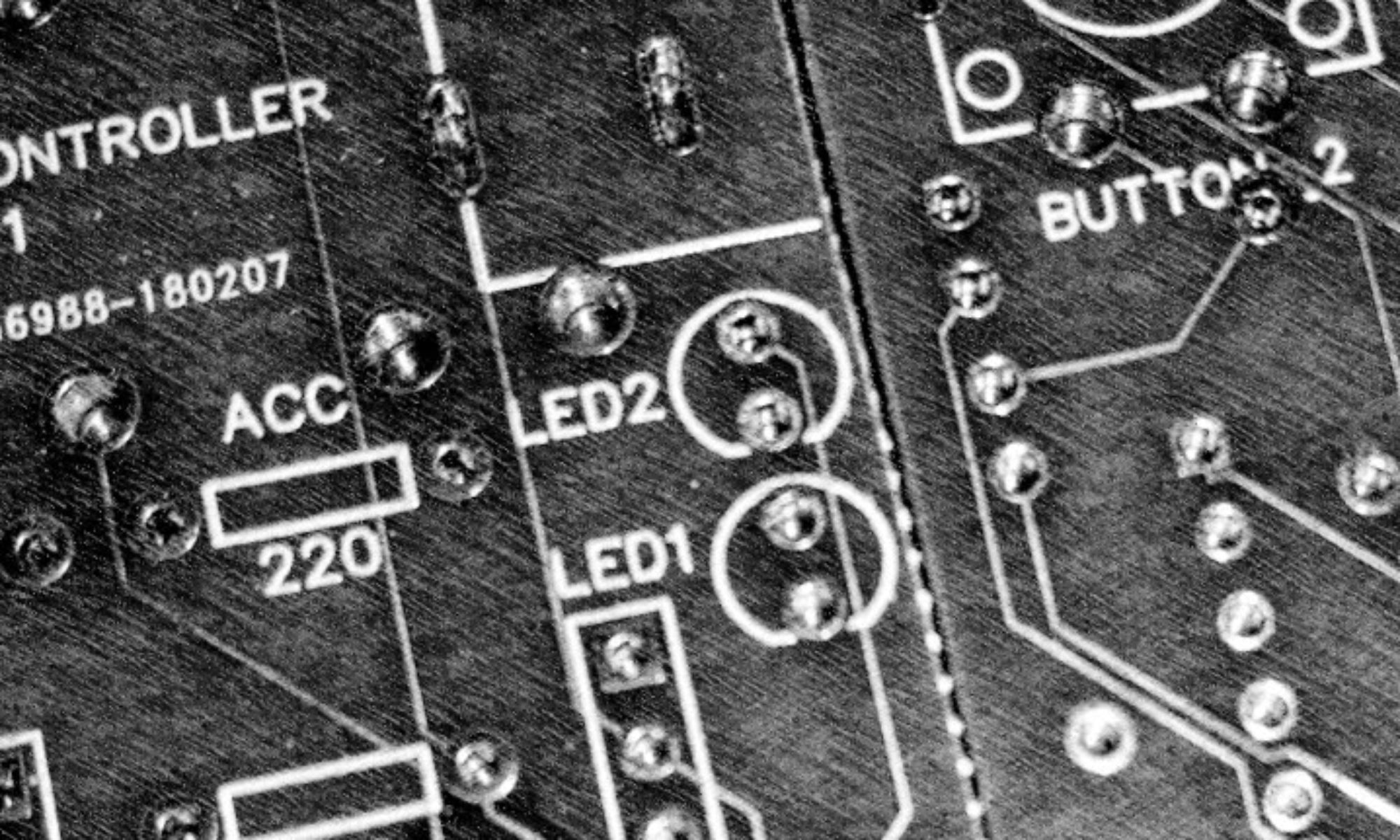
If you want to make your own blind controller but don’t want the hassle of the electronics or simply like the idea of a more compact and safe design, I have created a custom Printed Circuit Board (PCB) which can be purchased via eBay.

DSC00503

Assembly of the blind controller using the custom PCB boards is relatively straight forward, insert the listed components into the labelled slots and solder in place.  Here I’ve listed a few useful hints to save you a bit of time in the process and make sure everything goes smoothly…

Note: Everything but the two buttons are soldered to the same side of the board, check using the photos below before starting out and I advise checking components before soldering as removing them once they are in place can be difficult!

  • Solder the resistors: The resistors simply drop into place and should approximately match the indicated  ratings. Cut away any excess wire.

    C0032.Still001

  • Solder the DC jacks: It is important to do this before the buttons as otherwise you may find one of the button pins clashes

    C0032.Still002.jpg

  • Add header sockets for Arduino Nano and L298N Motor Driver: Solder 2x15pin female header sockets for the Arduino nano. Although the L298N motor driver can be dropped straight in to the board, you may want to consider using a header socket here too as these allows for easy replacement should this component ever fail. The positive pin of the L298N should be nearest the bottom edge of the PCB board.
  • Solder buttons: One button will slot into place without any modification. To save space the second button sits very close to the accessory jack. Cut off the leg whose mounting whole is blocked (this will not effect the working of the controller in any way)
  • Solder LEDs: Yellow at the bottom, green at the top, the short leg (cathode) of both leds should be inserted at the top (nearest the buttons).
  • Solder the RF reciever: This should slot into place with the GND pin nearest the bottom edge of the PCB board. You may want to consider using a header socket as used earlier but there may not be space in the current design to accommodate for this.
  • Insert Arduino: Slot the Arduino nano in place being sure that pin D12 of the nano is alongside the + pin of the L298N (You need to solder pins to your nano in such a way to achieve this).

    C0032.Still003.jpg

  • Upload the latest sketch: Attach the nano to the USB and upload the latest sketch using the Arduino IDE.
  • Connect motor and test: Connect 2 pins from the motor to the L298N, power the controller from the jack at the bottom of the board using a minimum 5V (Center pin positive). Note: The jack is labelled as 12V but I recommend a maximum voltage of 9V.

    C0032.Still004.jpg

  • If everything is working as expected, assemble the electronics inside the housing using screws or hot glue and complete the assembly of the blind controller. If something does not work or behaves unexpectedly check connections using a multi meter and replace any suspect components. I have had broken L298Ns and RF controllers in the past.
  • Calibrated the controller by pressing and holding the buttons to raise or lower the blind to the required start/end position, then (when the orange light is not lit) press and hold until the full extent of required travel has been achieved. Now whilst the orange light is lit hold down the same button and the controller will flash to confirm that this time has been saved to memory. Repeat for the other direction. This may take some time to get perfect, modification of timings in the sketch itself may be easier. An alternative solution is to install the magnetic end stop sensor using the accessory port, details of which can be found on thingiverse. Good luck!


Magnetic Sensor End Stop For the Automatic Blind Controller

The Blind Controller currently operates up and down blind movements based on calibrated times. This works fine most of the time but does require some patience to set-up and over time can drift resulting in the blinds over or under shooting their intended end point.

To solve this I have been working on a magnetic sensor that attaches to the accessory slot and requires only two small attachments to either end of the blind cord. The designs for these are available from thingiverse here. As well as the 3D-printed attachment you will also need the following:

The 3D Design:

The sensor in place:

DSC00500

The provisional Arduino script is available to download here for those of you who are keen.

Next up: Some housing for the sensor module and a generally ‘neater’ solution.


Custom Circuit Boards For Blind Controller

I have recently ordered a new batch of custom circuit boards for the Blind Controller. With these you only need to solder components where indicated saving on complicated wiring and making it easier to fit into the 3D printed housing. These will be available on eBay once they arrive and have been tested and will be limited so please check back frequently to secure one!

02643286-0fc4-468c-a798-8b05dc0ffb29_1_0_1


How to Crimp DuPont Cables

DuPont or jumper cables are used commonly in Arduino projects, for those components that do not come with DuPont connectors we must fashion our own. The process of adding connectors to the bare wire is known as crimping and it can be done most easily using a crimping tool. Here is a short guide to crimping DuPont cables using one of these to ensure you can get it right everytime!

The crimping tool I use is cheap and widely available:

https://www.amazon.co.uk/gp/product/B077RVK5JK/ref=as_li_tl?ie=UTF8&camp=1634&creative=6738&creativeASIN=B077RVK5JK&linkCode=as2&tag=tinted184-21&linkId=95febeb0d632e5796f812a60bf72d34a

You will also need some connectors:

https://www.banggood.com/Geekcreit-310pcs-2_54mm-Male-Female-Dupont-Wire-Jumper-With-Header-Connector-Housing-Kit-p-1063303.html?p=KF2715792233201409DJ

Examples of a crimped connector, bad (left), good (right):


First strip the wire exposing only 3-4 mm of wireDSC00395.JPG

This ensures that the connector will grip the plastic insulation and will have sufficient contact with the wire.

DSC00394.jpg

Place the connector within the 20-22 AWG slot of the crimping tool ensuring the ‘pin’ portion of the connector is outside of the tool.

Slowly close down on the crimp tool to slightly bend the connector, this is so that we can fit it into the 28-24 slow, do not fully crimp the connector! Release the connector by pushing on the ratchet release located between the handles.

Place the connector inside the 28-24 slot of the crimping tool and close down until it is just in contact with the connector, again making sure the pin portion is not inside the tool.

DSC00407.JPG

Place the wire inside the connector and ensure that 1-2mm of plastic insulation is inside the connector.

DSC00409.JPG

Clamp down on the tool, 2-3 times until it automatically releases ensuring that the connector does not rotate too much as you do.

DSC00410.JPG

Slide the connector into the desired plastic housing and you are done!